Hydraulic efficiency
Generally, fish-safe impellers cannot be modified, no trimming, or blade angle adjustment, therefore, pump performance must instead be matched to the application by adjusting the pump speed.
Variable Frequency Drives (VFDs) enable this speed control ensuring pumps are trimmed to perform at the best efficiency possible, whilst maintaining Fish Safety.
Electrical efficiency
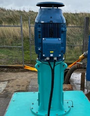
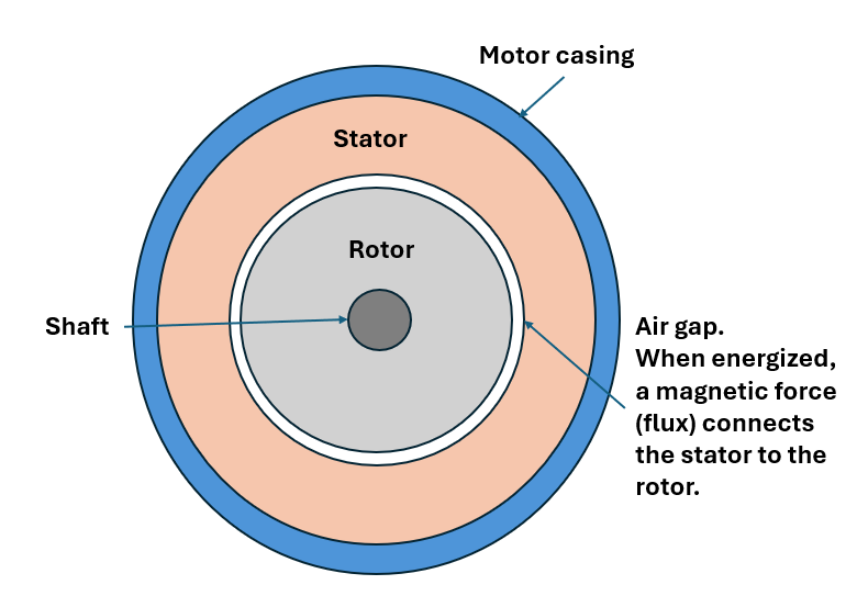
Fish-safe rotor dynamic pumps are designed to have low impeller tip speeds to minimise shear and turbulence helping protect aquatic life. Achieving these low speeds requires slow-speed, high-pole induction motors. While mechanically effective, these motors introduce electrical inefficiencies due to their inherently poor lagging power factor (PF). The magnetising current needed to establish the air-gap flux (gap between the motor stator and rotor) becomes disproportionately large relative to the torque-producing current, leading to poor displacement power factor and high reactive power demand.
Why is this an issue?
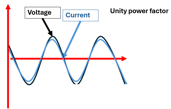
Apparent power is the total power supplied by the utility, measured in kilovolt-amperes (kVA). It consists of two components:
- Active power (kW) – the useful power that performs actual work, such as driving motors.
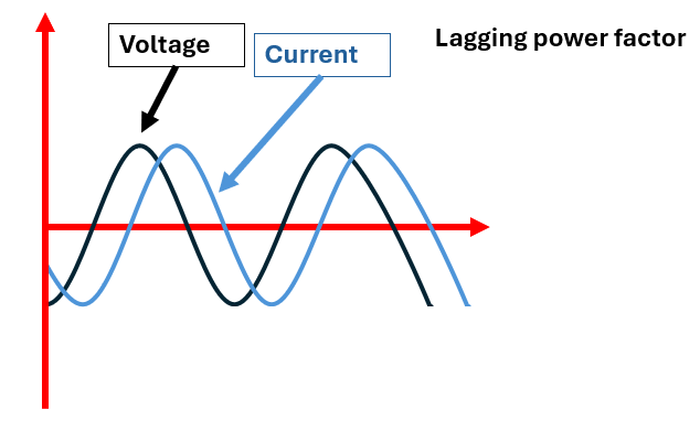
- Reactive power (kVAR) – the power associated with the magnetic and electric fields in inductive and capacitive equipment, caused by the out-of-phase component of voltage and current (as above image)
A low power factor (the ratio of active power to apparent power) increases the amount of current required to deliver the same amount of useful power. This leads to:
- The need for larger and more expensive conductors, cables and transformers
- Higher losses in the system due to increased current
- Reduced overall system efficiency
- Higher operational and energy costs
Effect on the PF when using a VFD
1. Motor Side (VFD → Motor)
- The induction motor still requires magnetising current and therefore shows a low displacement power factor at its terminals.
- However, the VFD internally supplies this reactive current (KVAR), so it does not need to be drawn from the grid.
2. Supply Side (Grid → VFD)
- The VFD rectifies the AC input, stabilizes it via a DC link, and reinverts to variable-frequency AC for the motor.
- On the grid side, the rectifier stage is designed so current is nearly in phase with voltage.
- The result: the grid sees a near-unity displacement power factor (≈0.95–0.99 lagging).
- Reactive power is contained within the VFD, not exported to the supply.
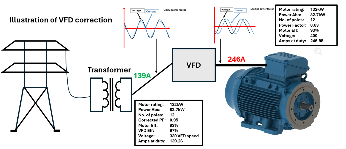
System Implications
- No external power factor correction needed: Capacitor banks or synchronous condensers are unnecessary for motors driven by VFDs.
- Hydraulic efficiency: Speed trimming with the VFD allows exact matching of pump performance to system demand, reducing throttling and bypass losses.
- Electrical efficiency: The VFD decouples the motor’s poor PF from the grid, avoids PF penalties, reduces upstream current, and improves transformer/cable utilisation.
- Net benefit: Although the VFD introduces a small conversion loss (~2–5%), the combined electrical + hydraulic efficiency gains usually far outweigh this penalty.